Major Components: Hoppers
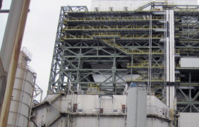
Precipitator hoppers are designed to completely discharge dust load on demand. Typically, precipitator hoppers are rectangular in cross-section with sides of at least 60-degree slope. These hoppers are insulated from the neck above the discharge flange with the insulation covering the entire hopper area. In addition, the lower 1/4- 1/3 of the hopper wall may be heated. Discharge diameters are generally 8″ – 12″.
- Insulation¨ “ Insulation provides protection for facility personnel and also works to retain as much hopper wall temperature as possible. Hopper wall temperature retention discourages condensation on the inside of the hopper. Heaters are added to ensure that metal surfaces immediately above the fly ash discharge are hot.
- Facilitating Hopper Discharge¨ “ Hopper discharge problems are caused by compaction of the fly ash in the hopper. Moisture content, particle size and shape, head of material, and vibration all affect PM’s compaction characteristics. The flow of PM out of the hopper can be facilitated by the use of external vibrators. These can operate on the outside wall of the hopper or on an internal hopper baffle.
- Hopper Fluidizers¨ “ Hopper fluidizers have a membrane that permits airflow to the PM directly above. This airflow fills the voids between the fly ash particles at a slight pressure, changes the repose angle of the particles, and promotes gravity flow.
- Ash Handling System¨ “ The fly ash handling system evacuates the fly ash from the hoppers, and transports the fly ash to reprocessing or to disposal. The ash handling system should be designed and operated to remove the collected fly ash from the hoppers without causing re-entrainment into the gas flow through the precipitator. The design of the ash handling system should allow for flexibility of scheduling the hopper discharges according to the fly ash being collected in these hoppers.
Either the precipitator hopper or the feeder hopper is used for temporarily storing material prior to discharge. Three types of handling systems are in use:
- Negative Pressure or Vacuum System “ Connects to the hopper by a simple discharge valve
- Positive Pressure Dilute Phase System “ Uses an airlock-type feeder; the feeder is separated from the hopper by an inlet gate and from the conveying line by a discharge gate
- Positive Pressure Dense Phase System “ Connects to the hopper with an airlock type feeder.
Helpful Resources
KnowledgeBase: Reduce ReEntrainment
Our Capabilities: Hopper Evacuation & Optimization


